Distributed Alarm Annunciation & Sequence of Events Recording - The Why and How.
By Ian Loudon
Root cause analysis is the main driving force behind Sequence of Events (SOE) Recording and the determination of what caused the plant to trip. The Cost of downtime motivates the expenditure on equipment to diagnose quickly what happened so corrective action can be taken. Downtime Costs can run into millions per hour on big plants with even a seemingly insignificant but crucial area of the plant causing a knock-on effect to the rest of the enterprise.
The issue here is to have available the status of key parameters (normally Relay Contacts) due to the nature of safety shutdown systems/ plant trip systems. Analogue signals are often also of interest in analyzing what happened too, in many cases these are derived from Analogue set-points as relay contacts, but more modern SOE systems now have the ability to integrate the Analogue signals too directly.
So my trend screen on SCADA or DCS will show me what happened?
No,unfortunately this is not the case as the scan time is not good enough to give engineers the resolution of which device tripped first especially in a shutdown where many statuses change together. Scan time on SCADA is based on how many I/O on the system and how busy the Computer is with tasks. Many good systems aim for a few seconds resolution, this is simply not good enough for Sequence of events determination.
My PLC has a 1micro second instruction cycle can I use this?
While this specification seems impressive it also depends on how many I/O it supports and what control philosophy is running. A 1000 line program already slows this PLC to 1millisecond and it has not handled any communications delays yet.
Best Practice
The event i.e. change of state is date and time stamped at the front end device
- the SER. This message is delivered to the network where it is transferred to a database on the SCADA or DCS system normally via an OPC server, which makes this efficient and fast. From there the sequence of events can be analyzed because they are all chronologically sorted. Network delays do not affect the data integrity. Most Important! The SOE or SER device (Sequence of Event Recorder) as they are known, process the inputs with the ability to discriminate between input changes of state to 200micro seconds, even if there are 32 or 4800 inputs. They are designed to scan inputs in the sub millisecond range, independent of the number of inputs on the system thus the Input count has no effect on the resolution of the system. Obviously this is not how PLC architecture or SCADA and DCS architecture works. The event recorders purpose is to deliver the events with their date and time stamp to the supervisory system as fast as possible. In the event of a plant shut down the history can be reviewed as a chronological history of all monitored points with a 1milli second resolution from a time before the trip to a time after the trip. The sequence of events allows engineers to find out the first event preceding the trip and to be able to home in on that area of the plant to rectify the problem in the minimum possible time. Law and procedure often prevents them restarting the plant without first having diagnosed the cause of the trip.
Time stamp at source to better than one milli-second is the mark of Quality on an SOE system and is the industry benchmark standard. Using an SOE system compliments the SCADA and DCS functionality by providing accurate data and enables plants to save by minimizing downtime.
Omni-4000 & Maxiflex SOE
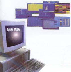
The latest Omni-4000 package released by Omniflex is a PC/windows based Critical Real-Time Alarm Events Monitor, which performs two main functions, Distributed Alarm Annunciation and Real-Time Sequence of Event Recording.
"Vital information to facilitate downtime savings and predictive maintenance"
Omni-4000 integrates both the Alarm Annunciation and Real-Time Sequence of Event Recording into one PC based package with a host of features, providing users with the ability to monitor alarms and retrieve a log of real-time events for analysis, helping to determine what and why the events occurred. This information is vital to facilitate downtime savings and predictive maintenance.
"Operator friendly Global Alarm screens with enhanced details"
Omni-4000 has a useful multi-level alarm display enabling the operator to view the areas in alarm condition in a progressively enhanced detail. From a global screen displaying 1200 alarm points the operator can view the actual individual alarms, complete with real-time time stamped data and the alarm status i.e. if the alarm has been acknowledged, silenced, cleared or is in a normal state.
"Sub 1ms time-stamping of Alarms"
The Omni-4000 package is designed to operate with front-end equipment in sequential events recording applications that are capable of time stamping the events as they occur at the input in the field. This is important as on many other distributed systems, the events transmitted over a local area network to a supervisory PC may not necessarily be in true chronological order when received, due to network delays and data volumes on the network. When using the Omni-4000 Software with Omniflex front-end equipment such as the Maxiflex Sequence of Events system the events are time-stamped to sub 1ms resolution by the Maxiflex SOE input modules in the field and these events are then sorted chronologically at the PC by the Omni4000 software. Omni-4000 also time stamps the operator's response to alarms I.e. on pushbuttons, enabling operator response times to be monitored to.
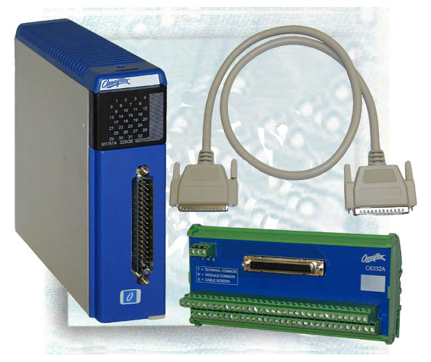
The complete SOE Solution from Omniflex
A complete distributed Real-Time Sequential Event Recording and Alarm Annunciation system from Omniflex consists of a Maxiflex SOE system networked and configured to drive local Annunciator displays (if required) and feed the events to the PC based Omni-4000 system. Annunciator pushbuttons can be field mounted (up to 150 sets of buttons) or Omni-4000 based with the option to transfer control to either.
A significant benefit over other PC based systems is the ability to configure Omni-4000 while the system is on line. When put into engineering mode, the package is still live and the operator is still alerted to any change in status of alarms in an active window, which are always present on screen.
Omni-4000 is also capable of running on Omniflex's unique well proven Conet industrial token-passing local area network, which operates over twisted pair cable or even spare cores in existing multi-core cables. As a single network this can be up to a distance of 10km with no limit on the number of inter-connected networks and network types, providing a very flexible network infrastructure.
Omni-4000 & Maxiflex SOE Summary
Summary
- Windows OS/PC based
- 4800 point Alarm annunciator and Real-Time Event Monitor
- 1200 alarms viewable on one screen
- Real Time time stamping of Alarm & events to sub 1mS at source
- Active window for Live Event displays
- Customised Alarm reporting
- On-line configuration
- Field Proven
- 35 years of experience
- Automatic daily backup of data
- Local Display Fascia's with Pushbuttons
- Local Alarm Panel Options
- Maxiflex allows Analogue and Digital Inputs for SOE
- 1000 Event buffer for every 32Channel SOE module
- Programmable Input filtering
- Any SCADA Interface via OPC Server
Last Month:
Last month we talked about several important topics including:
- Distributed Alarm Annunciation & Sequence of Events Recording - The Why and How.
- Omni-4000 & Maxiflex SOE
- The complete SOE Solution from Omniflex
- Omni-4000 & Maxiflex SOE Summary
If you missed these or other key discussions,
you can find the back issues on the newsletters
page of our website:
Subscribe/Unsubscribe
Subscribe to Omniflex News
Unsubscribe from Omniflex News
This publication may be freely redistributed if copied in its ENTIRETY. Portions
of this newsletter may be reprinted with permission.
(c)
Copyright 2003 OMNIFLEX PTY LTD |