Web Based Remote Monitoring
Reliable Web based solutions for monitoring the condition or status of remote assets no matter where you or they are located.
Read more...
Reliable Web based solutions for monitoring the condition or status of remote assets no matter where you or they are located.
Read more...
SIL rated alarms systems, wireless telemetry and web based inventory tracking systems. Connects to your existing tank gauging.
Read more...
Advanced proven Impressed Current Cathodic Protection Systems incorporating Remote Monitoring and Control. New or retrofit existing sites.
Read more...
Specialised monitoring systems for Radiological environments including
nuclear power stations, storage facilities, PET
Centres etc.
Read more...
Real time energy, water, gas, air and/or steam monitoring for industry, commercial buildings and campuses. Meets reporting standards and reduces cost.
Read more...
Remote Temperature monitoring systems tailored for pharmaceutical and food industry applications from laboratories to warehousing. Meets reporting standards.
Read more...
Process Alarm Systems to IEC61508 and Event recording to sub-millisecond resolution making plants safer and reducing downtime.
Read more...
Upgrade your legacy alarm systems to current safety standards with minimum plant disruption. Custom solutions to suit individual needs.
Read more...
Data2Desktop provides an end-to-end solution to your remote
monitoring needs. Data2Desktop relieves you of the technical
complexities of implementation, with rapid low risk deployment.
Turn your organisation into a Real Time Enterprise within days.
more...

Remote Monitoring Specialists
Instrument PSUs

Priced to perfection
DIN Rail mounted
All Round Protection
Adjustable 24Vdc o/p
Support > Knowledgebase Article K37
Ask for assistance:
Please provide us valuable feedback on this article or product:
Make a sales enquiry:
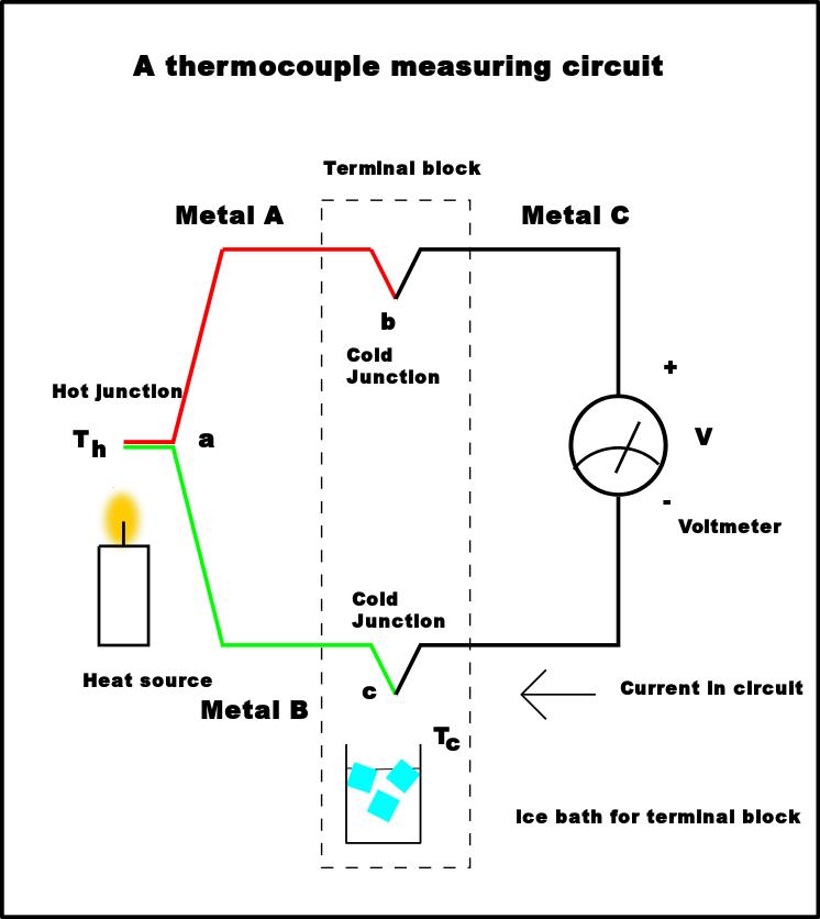
Thermocouples are temperature sensors, which consist of two different wires made of specially selected metals or alloys. The wires are joined at one end and this end forms the actual sensor and measurement point. Often this joint is placed in the tip of a specially constructed temperature probe for protection. The open circuit voltage, or "emf", measured across the other "open" ends of the two thermocouple wires is approximately proportional to the temperature difference between the location of the probe (the joined end of the two wires) and the point where the "open" end is located.

Thermocouples are inexpensive, simple, durable, extremely repeatable, and relatively accurate. They can measure temperatures from nearly absolute zero to about 2500 degrees C (about 4500 degrees F). A few important comments will help "understand" thermocouples and the terminology, namely:
Product Ranges